Overview
Platform: Raspberry Pi + ICO FPGA Board + Exp-Board
Language: VHDL
Author: Abel Paul John
In this project, I implemented four VHDL designs on an FPGA and verified each one directly on real hardware. The goal was to move step by step from basic combinational logic to time-based digital systems. For every task, I wrote the VHDL code, synthesized it, programmed the FPGA, and confirmed the behavior by observing the RGB LEDs and LED row on the Exp-Board. The images below are live hardware proof that each task worked as intended.
Task 1 – Combinational Logic with Buttons (Minterms/Maxterms)
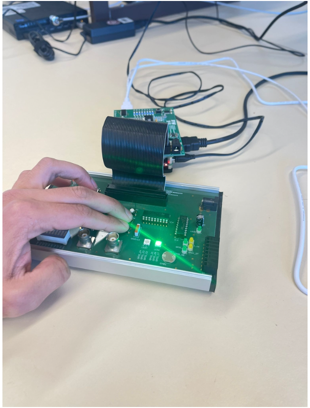
In the first task, I built a purely combinational design where the outputs depend only on the current input buttons. LED7 was controlled only by one switch, so it turned white when the switch was active and turned off when it was not. LED6 changed color depending on how many push buttons were pressed, which made it easy to test correctness because every input combination produced a clear visual result. After programming the FPGA, I tested multiple button combinations and confirmed that the LED behavior matched the intended logic every time.
Task 2 – Function Table Logic with an 8-bit Counter

In the second task, I used a clock divider and an 8-bit counter to create time-dependent LED behavior. The counter continuously counted through values, and specific value ranges activated specific colors on LED6 and LED7. This task was important because it showed how to implement larger logic conditions cleanly using comparisons instead of writing long Boolean expressions. When I ran the design on hardware, the LEDs changed colors exactly at the defined counter intervals and repeated continuously without glitches.
Task 3 – Sequential Bit Pattern Generation
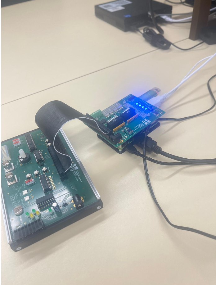
In the third task, I created a repeating LED pattern using a process-based sequential design. Instead of reacting only to inputs, the design advanced step by step over time using a counter. The LED row displayed an alternating pattern such as 10101010, and then reversed to 01010101, creating a clear moving visual effect. This task helped me understand how FPGA designs can be made “time-controlled” using clocked processes, and the hardware output confirmed that the sequence progressed smoothly and repeatedly.
Task 4 – PWM for RGB LED Brightness Control (FSM-based)

In the fourth task, I implemented pulse width modulation to control LED brightness using digital logic. I generated PWM signals using counters and finite state machines and connected the duty cycle to DIP switch values. When I changed the switches, the brightness of the LED channels changed smoothly, showing that the duty cycle control worked correctly. This task demonstrated an important real-world concept because PWM is widely used in embedded systems to control motors, LEDs, and power electronics efficiently.
Conclusion
This project demonstrates that I can design, implement, and verify VHDL systems on real FPGA hardware. Across the four tasks, I showed strong understanding of combinational logic, counter-based control, sequential processes, and PWM using state-machine design. Most importantly, each design was tested on physical hardware and confirmed visually, which proves that the implementations were not only correct in theory but also reliable in practice.
End of Case Study.
View all projects