Hardware Assembly & Soldering: 3×3×3 LED Cube
Overview
Platform: Arduino Nano
Author: Abel Paul John
Hardware Assembly & Soldering

This project involved the complete manual assembly and soldering of a 3×3×3 LED cube on a custom PCB. The cube contains 27 LEDs arranged in three layers and is controlled by an Arduino Nano. This image shows the final assembled hardware after soldering, integration, and functional testing. The goal of this task was to transform a schematic design into a stable, working three-dimensional LED system.
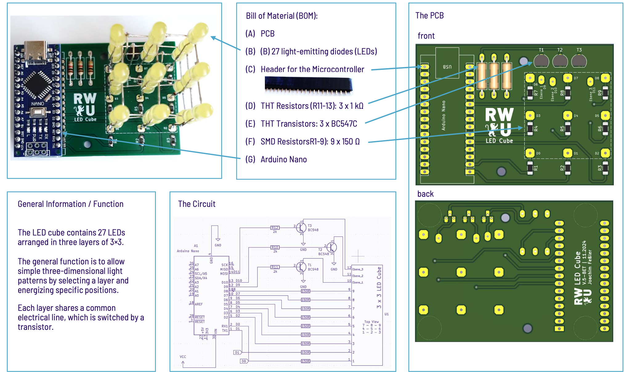
Before starting the soldering process, I carefully studied the circuit architecture. Each LED layer shares a common electrical line that is switched using a transistor, while the Arduino selects individual LEDs within the active layer. This multiplexing principle allows the cube to display three-dimensional light patterns. Understanding the switching structure was essential to avoid polarity errors and incorrect transistor orientation during assembly.

The assembly began by bending and soldering the 27 LEDs into three separate 3×3 layers. Each layer was tested before stacking to ensure electrical reliability. After constructing the cube structure, I soldered the SMD resistors, THT resistors, and BC547C transistors onto the PCB. The final step was mounting the cube onto the board and performing a complete functional test. The finished system demonstrates clean soldering quality, proper alignment, and reliable transistor-based layer switching.
Conclusion
This project demonstrates hands-on hardware skills, including precision soldering of both SMD and THT components, mechanical alignment of a three-dimensional LED structure, and complete system integration. It reflects my ability to move from theoretical circuit design to a fully functioning physical prototype.
End of Case Study.
View all projects