Overview
Laboratory: RC High-Pass and Low-Pass Filters
Author: Abel Paul John
Oscilloscope Analysis
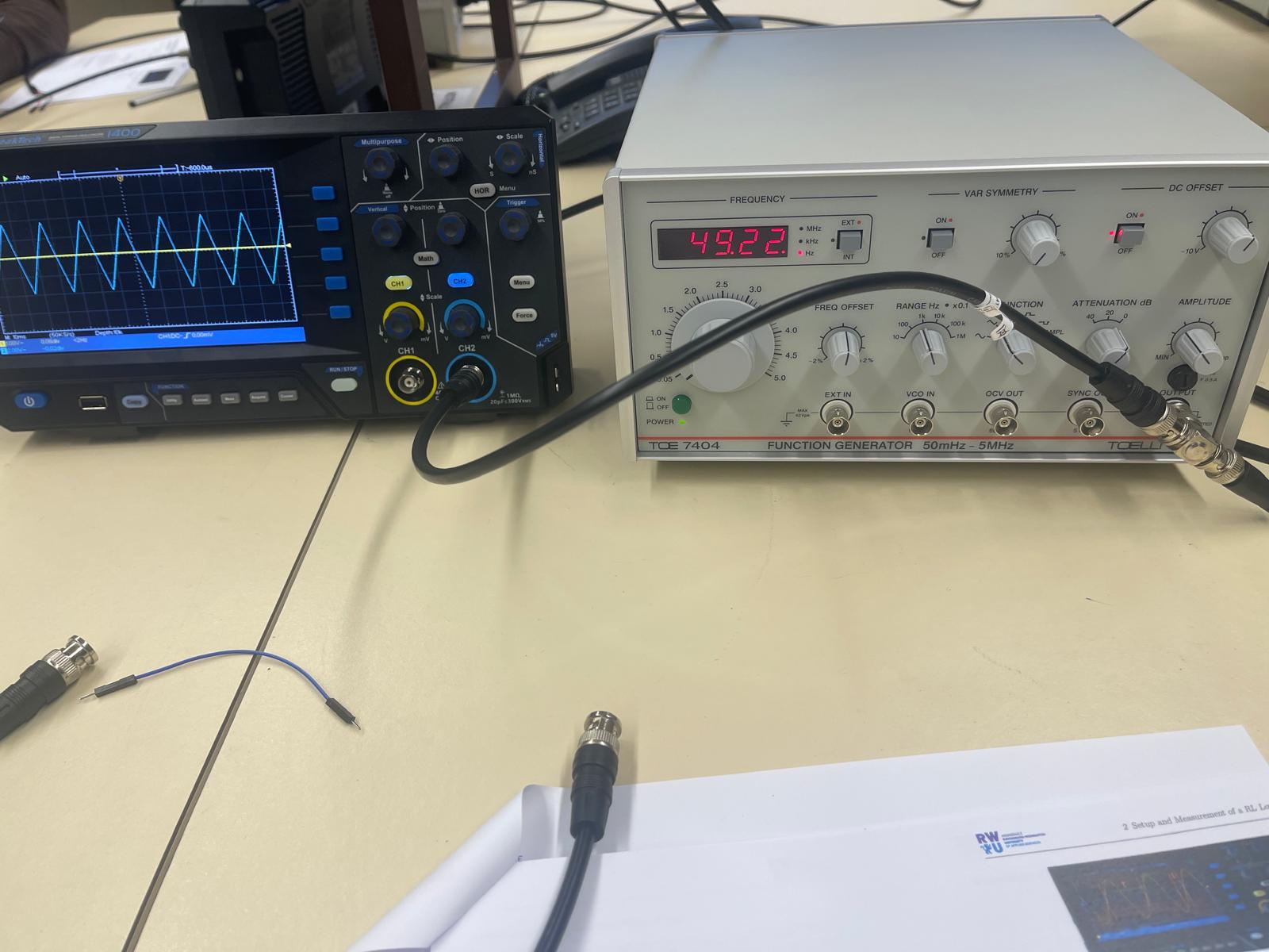
This experiment focused on analyzing the behavior of RC high-pass and low-pass filters using a function generator and an oscilloscope. A sinusoidal input signal was applied to the circuit, and both the input voltage and output voltage were measured simultaneously. The oscilloscope display shows the waveform and frequency in real time, allowing direct observation of amplitude changes and phase shifts between the signals.
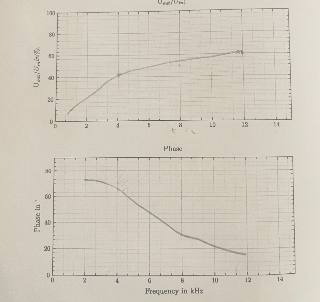
The high-pass filter was built using a resistor and capacitor connected in series. At lower frequencies, the output voltage is significantly reduced, while higher frequencies pass through more easily. By measuring the period of the waveform and the time shift between input and output, I calculated the measured frequency and phase difference. This allowed me to verify the theoretical behavior of the high-pass filter and observe how signal attenuation changes with frequency.
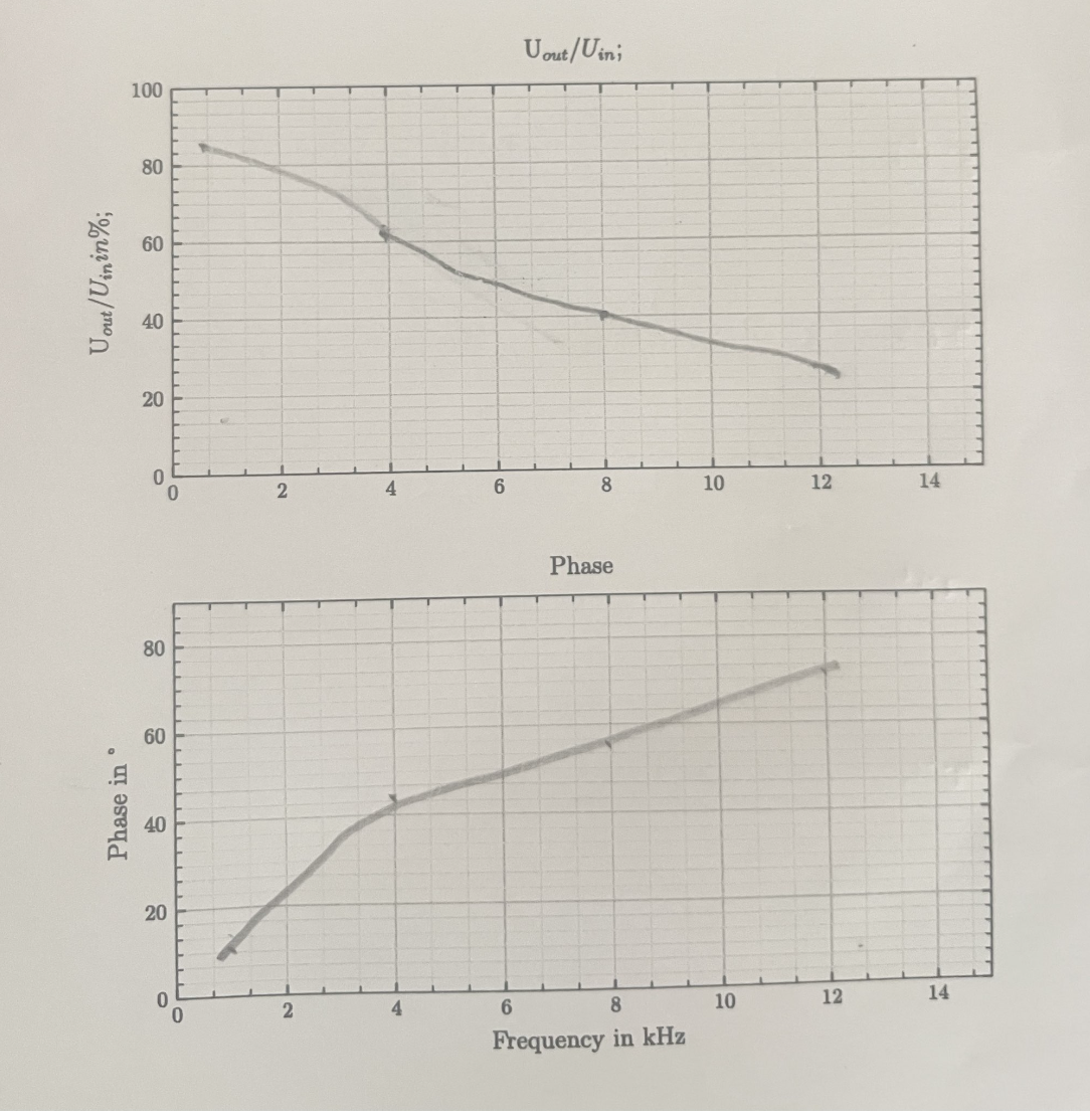
The low-pass filter was constructed using the same components arranged in a different configuration. In this case, low frequencies pass through with minimal attenuation, while higher frequencies are reduced. The oscilloscope was adjusted to display one full period of the signal to ensure accurate measurement of amplitude and phase shift. The experiment confirmed the expected frequency response and demonstrated the practical difference between high-pass and low-pass filter behavior.
Conclusion
This laboratory task demonstrates practical skills in signal measurement, waveform analysis, and frequency response evaluation. It shows my ability to connect theoretical transfer functions with real electrical measurements and to analyze analog circuits using professional laboratory equipment.
End of Case Study.
View all projects